Steps to a Successful Project
Design Inputs
The first step in a successful project is agreeing on the
design inputs. This can range from passing a simple sketch
on scratch paper at one extreme to instrumentation and
testing of an existing machine. The more complete and
accurate the design inputs, the better the final design will
be. We invite you to Fairfield or we will come to your
location. Or this can even be handled by phone, FAX, email
or other means of correspondence as long as we can reach an
understanding on your desired results.
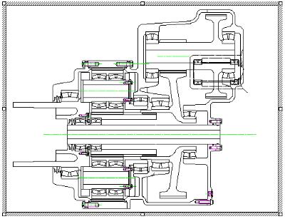
Step 2 Concept Design
During this stage gears and bearings are sized and rough
calculations are made for structural components. Either a
solid model or a 2-D section drawing is made for
presentation to the design review group. A rough order of
magnitude cost is generated and approximate lead time
estimated.
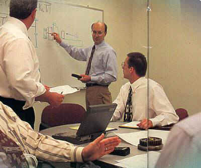
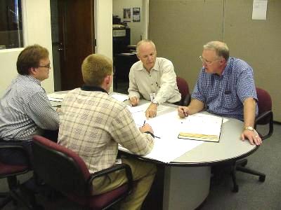
Step 3 Design Review
During this stage gears and bearings are sized and rough
calculations are made for structural components. Either a
solid model or a 2-D section drawing is made for
presentation to the design review group. A rough order of
magnitude cost is generated and approximate lead time
estimated.
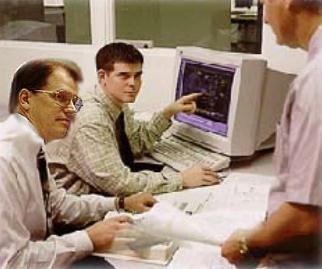
Step 4 Detail Design
During this phase, all engineering calculations are reviewed
and finalized. Structural FEM analysis is performed as
required to optimize material and strength. Dimensional
analysis is performed and all stack-ups recorded in the
project book for future reference. Work up to this point is
usually done using ProE or SolidWorks solid modelers. The
final task in this phase in to produce 2D part prints.
Step 5 Final Design Review & Order Approval
With the previous work completed, a final review meeting in
convened and a last check made to insure that the project is
ready to enter for manufacturing order. All design work is
maintained in a project book. In addition, a full set of
detail part prints, a section assembly print, a bill of
material and first time assembly procedures are products of
the process thus far completed.
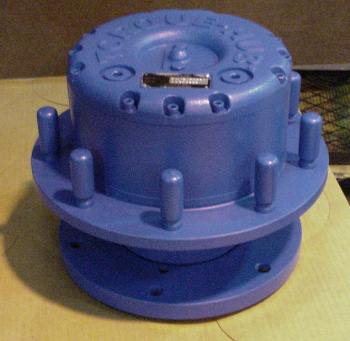
Step 6 Manufacture Prototype
Once an order is entered, the prints are submitted to
Manufacturing Engineering for process planning which
includes a production routing and inspection plan, durable
and perishable tool design and determination of
manufacturing sizes for the part. A shop print is drawn
using the design print as a starting point. Material is
ordered and the work scheduled in the shop.
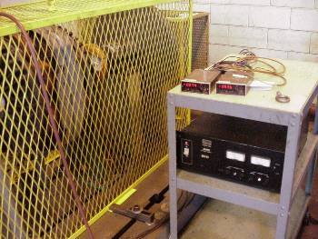
Step 7 Test
Some testing of the prototype is normally required to verify
that the design inputs and outputs match. We offer dyno
testing to 40 hp in our lab using eddy current loading for
unidirectional testing or flywheel inertia loading for high
cycle bi-directional operation. Various other structural
static cycling stands are available for non-rotating tests.
We also offer supervision and data collection of field tests
on customer's machines.
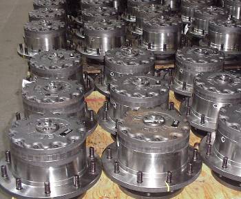
Step 8 Production
Our goal is production and once the
design is complete and verified, Fairfield has facilities to
produce components or assemblies in quantities from a few
parts to thousands.